
A USB device measurement system for the classroom
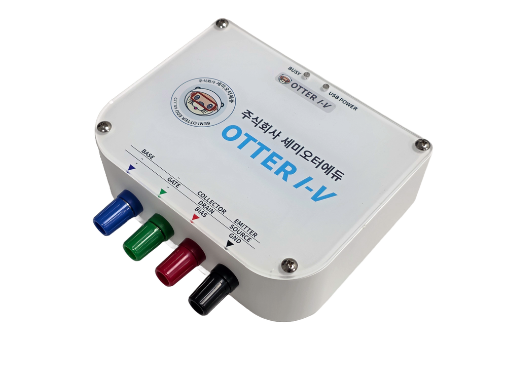
OTTER I-V
Plug it into a laptop over USB and measure the device sitting on the breadboard.
- ±10 V
- Source voltage
- ±8 mA
- Measured current
- 8 routines
- From diodes to memristors
- USB
- Bus powered · no separate adapter
From diodes to memristors, with off-the-shelf devices
The PC application and the tablet screen offer the same eight measurements with the same settings. The three memristor routines were added in application v1.2.0 in 2026.
| Routine | What it measures | Typical devices |
|---|---|---|
| I-V | Sweeps the voltage and measures the current. Single, double or cycle sweep | Resistors, diodes, LEDs, memristors |
| FET Transfer | Transfer characteristic against gate voltage at a fixed drain voltage | n- and p-type MOSFETs |
| FET Output | Drain current against drain voltage, stepping the gate voltage | n- and p-type MOSFETs |
| BJT Collector | Family of collector curves, stepping the base current | NPN and PNP transistors |
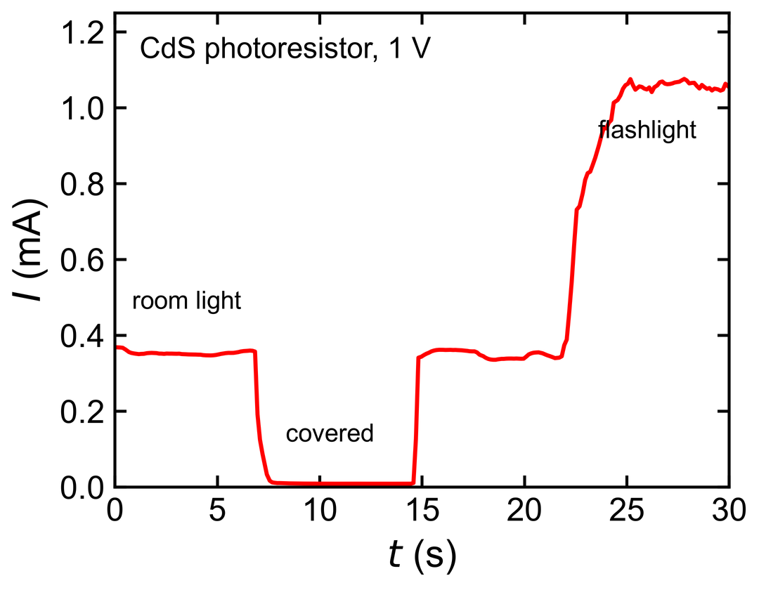
| I-t | Current against time at a constant voltage | Photoresistors and other light-sensitive devices |
| Retention | Whether a state written by a pulse holds over time | Memristors |
| Endurance | Repeats SET, read, RESET, read and tracks the resistance window | Memristors |
| P-D | Conductance change under repeated identical pulses (potentiation and depression, LTP / LTD) | Memristors, synaptic devices |
- Resistors 0.1, 1 and 10 kΩ — Ohm's law, series resistance
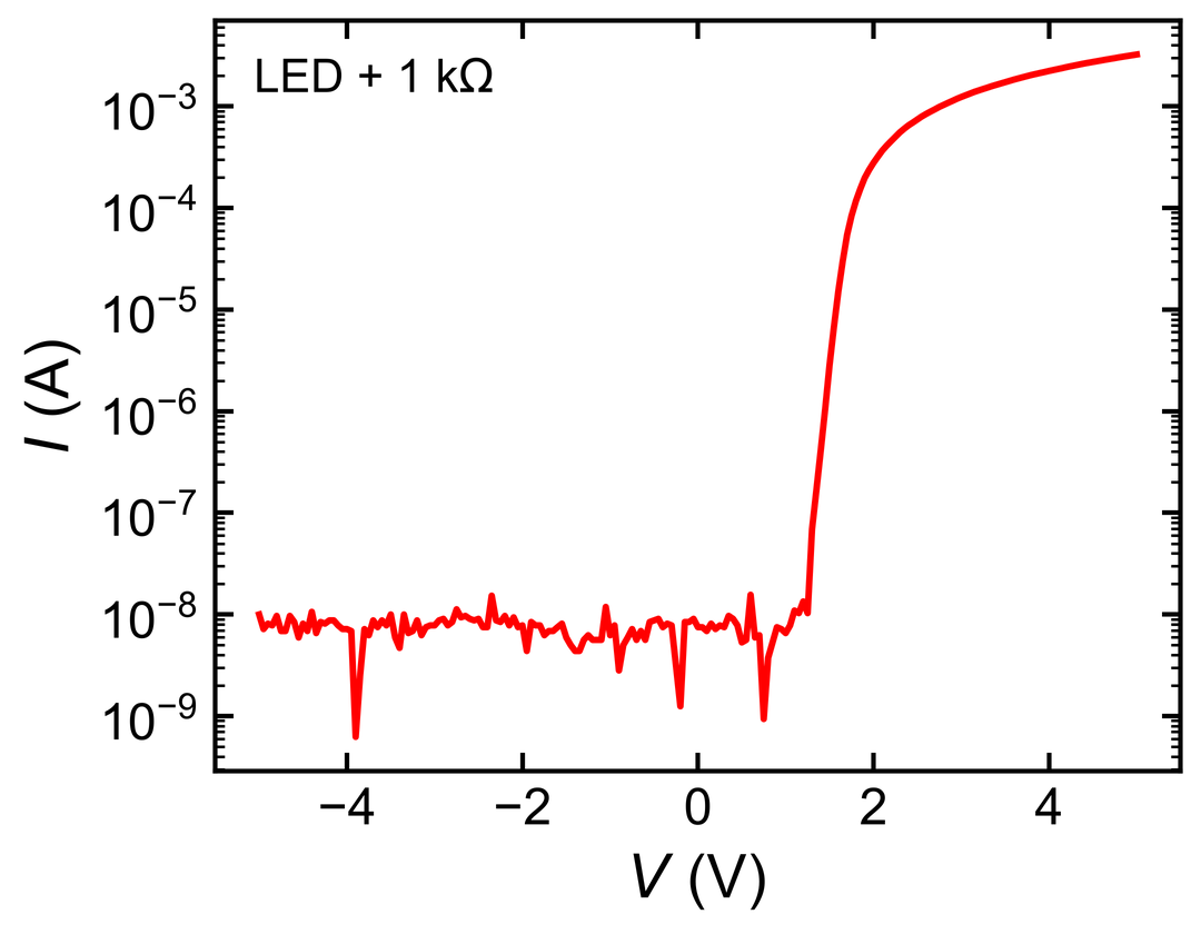
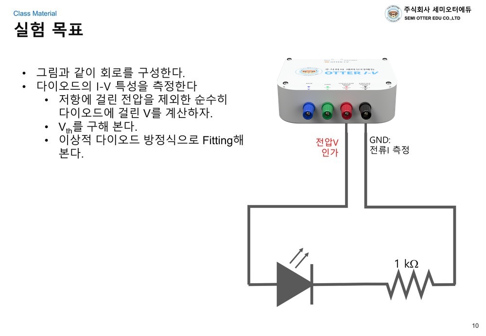
- Light-emitting diode — rectification, threshold voltage
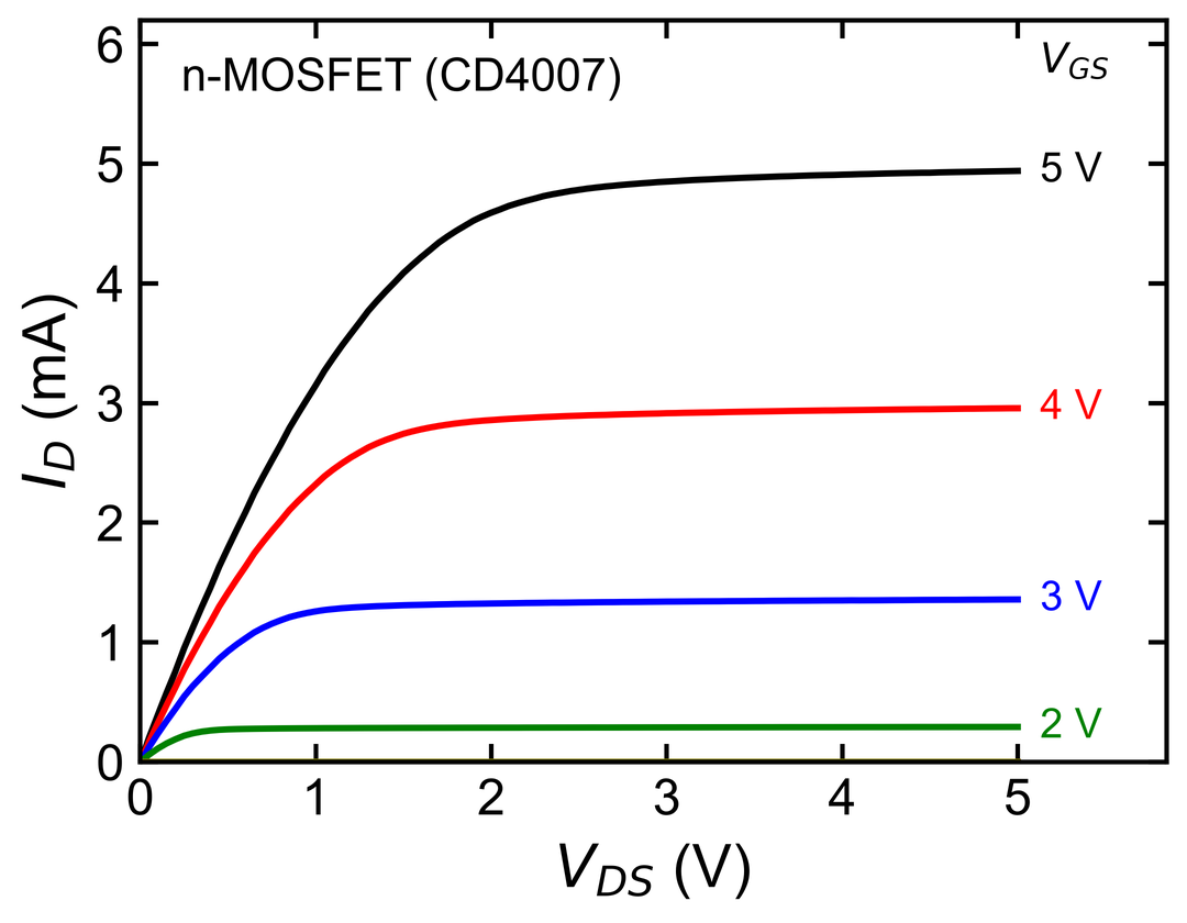
- CD4007 — n-MOSFET transfer and output characteristics
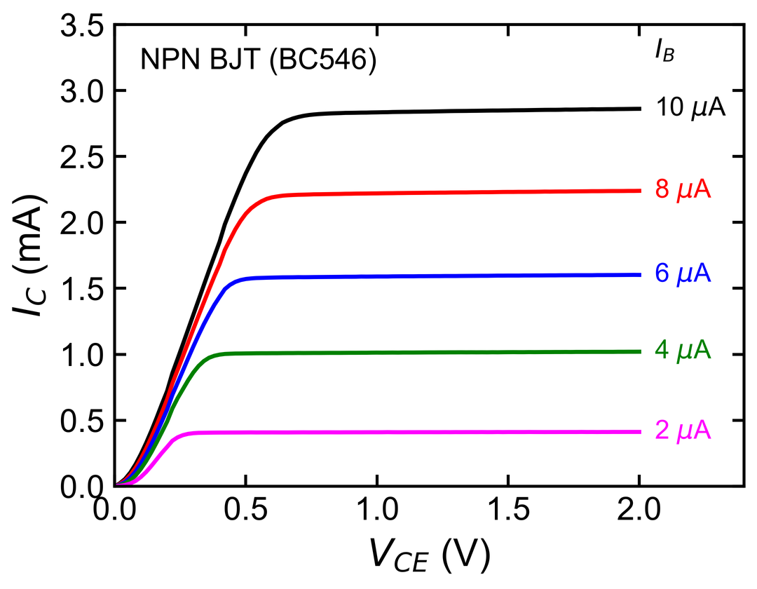
- BC546 — NPN BJT collector characteristics
- Photoresistor — light and resistance, I-t
They plug straight into the breadboard. Being commodity parts, consumables cost little.
A semester of lab work comes with the instrument
There is no need to write handouts from scratch. A semester's worth of handouts written for Otter I-V and the included test devices is supplied with it. Every graph below was measured with Otter I-V.
Diodes and LEDs
MOSFET
BJT
Semiconductors and light
Theory → Objective → Guide → Measure and analyse
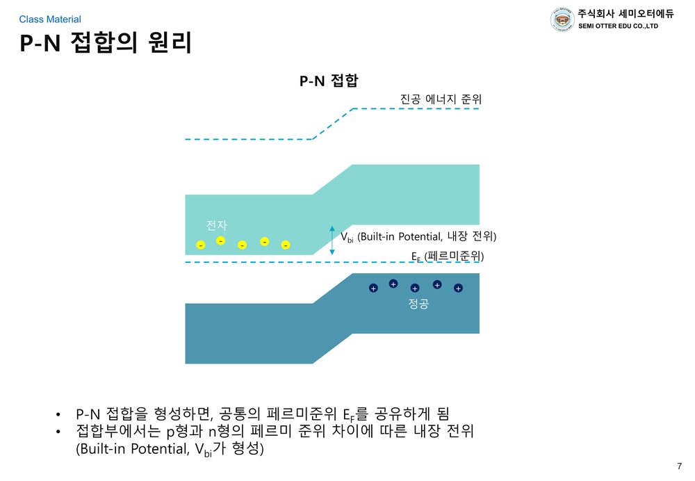
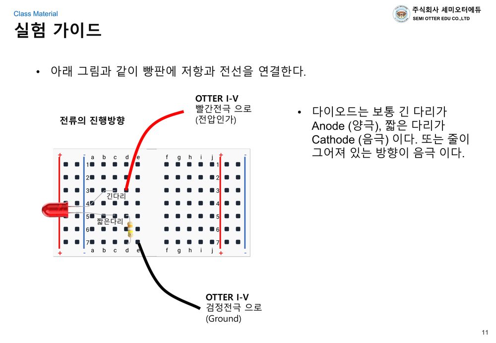
Every lesson follows the same order. The diode lesson is shown below as an example.
How a P-N junction works
Circuit, quantities, analysis
Breadboard wiring
Students measure for themselves
They open the csv in a spreadsheet or Python, find the threshold voltage and fit the ideal diode equation.
Lesson plan
- 0Ohm's law primerCourse introduction · resistors and first measurements
- 1DiodeP-N junction · LED
- 2MOSFETCD4007 transfer and output
- 3BJTBC546 collector characteristics
- 4Semiconductors and lightPhotoresistor · light
- +MemristorRetention · endurance · potentiation and depression (supplementary)
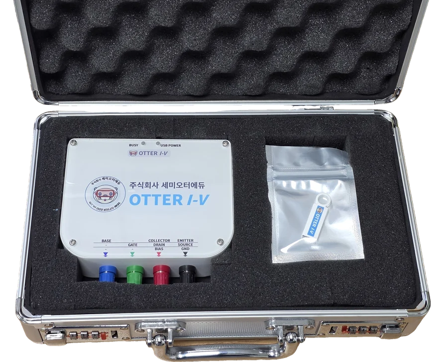
Instrument, devices and handouts together
- Otter I-V unit, USB cable, USB A to C adapter
- Banana-to-jumper cables, breadboard
- Test devices — resistors 0.1 / 1 / 10 kΩ, light-emitting diode, CD4007, BC546, photoresistor
- Software on a USB stick, four lab handouts
- ABS case — holds the unit and the accessories
Your university or department logo is printed on the unit when you order.
Units are kept in stock and ship within five business days of the order. Please check with us first for large orders.
An application on the PC, a browser on the tablet
The tablet opens the instrument in a browser with no app to install. Both offer the same measurements.
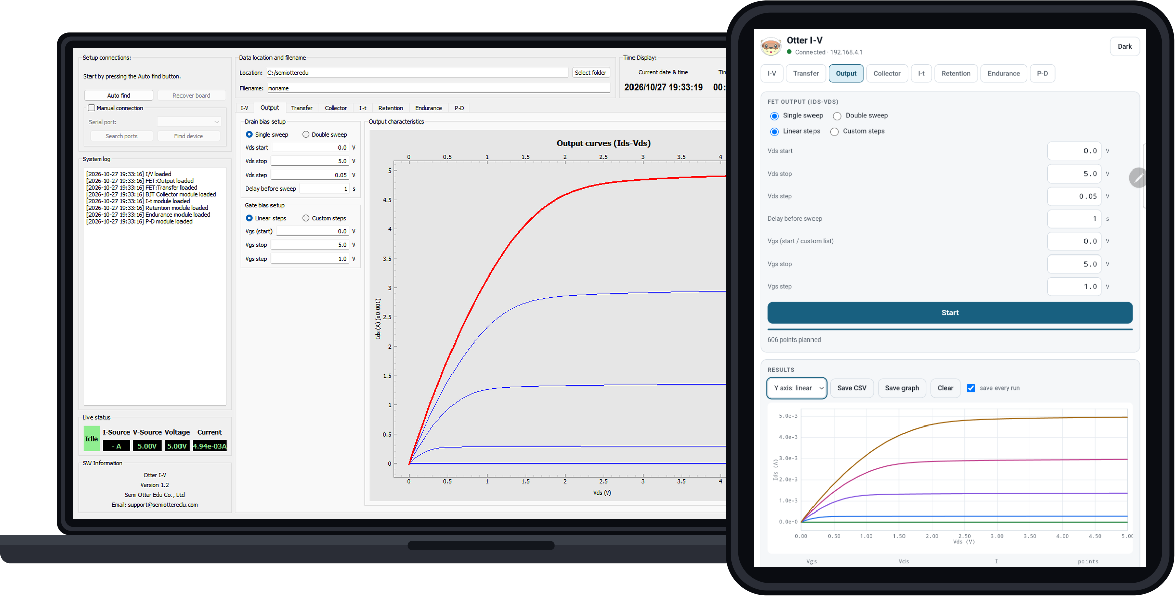
- USB — measure with the Windows 10 / 11 application and save the result as csv.
- Wireless — the instrument opens its own wireless network and serves the control screen itself. Open it from the browser of an iPad, an Android tablet or a laptop.
Connecting a tablet in three steps
- Join the instrument's Wi-Fi
The instrument creates the network itself. No router and no internet connection are needed. - Enter 192.168.4.1 in the browser
The control screen lives inside the instrument, so there is nothing to install. - Measure → csv and png saved automatically
The data and the graph land in the tablet's Download folder.
Wireless works the same
- No computer, no installation and no internet connection.
- A 100-point measurement takes 2.4 s, the same as over USB.
- If the screen is closed or the connection drops, the output returns to 0 V.
- Units already in use gain wireless operation by running the setup program once, in about a minute.
Four 4 mm banana jacks
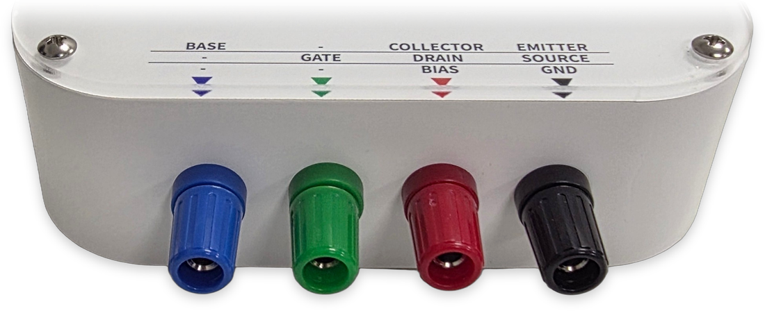
| Blue | Current source 0 to 200 µA |
|---|---|
| Green | Voltage source ±10 V |
| Red | Voltage source ±10 V |
| Black | Current measurement |
Specifications
| Voltage source | ±10 V (drain / collector, gate) |
|---|---|
| Current source | 0 to 200 µA (BJT base) |
| Current measurement | ±8 mA, resolution limit approx. 100 nA |
| Measurement routines | 8 — I-V, FET Transfer, FET Output, BJT Collector, I-t, Retention, Endurance, P-D |
| Connection | USB-C, Wi-Fi (tablet browser) |
| Power and connectors | USB bus powered (no separate adapter), four 4 mm banana jacks |
| Software | Bundled application (Windows 10 / 11) · tablet browser screen (nothing to install) |
| Data | PC: csv / tablet: csv and a png graph. Saved automatically when the measurement ends |
Considering the instruments for your lab?
We arrange demonstrations, quotations and technical support for Otter I-V and Otter I-V Expert.